Step 1: Gather and Inspect Components
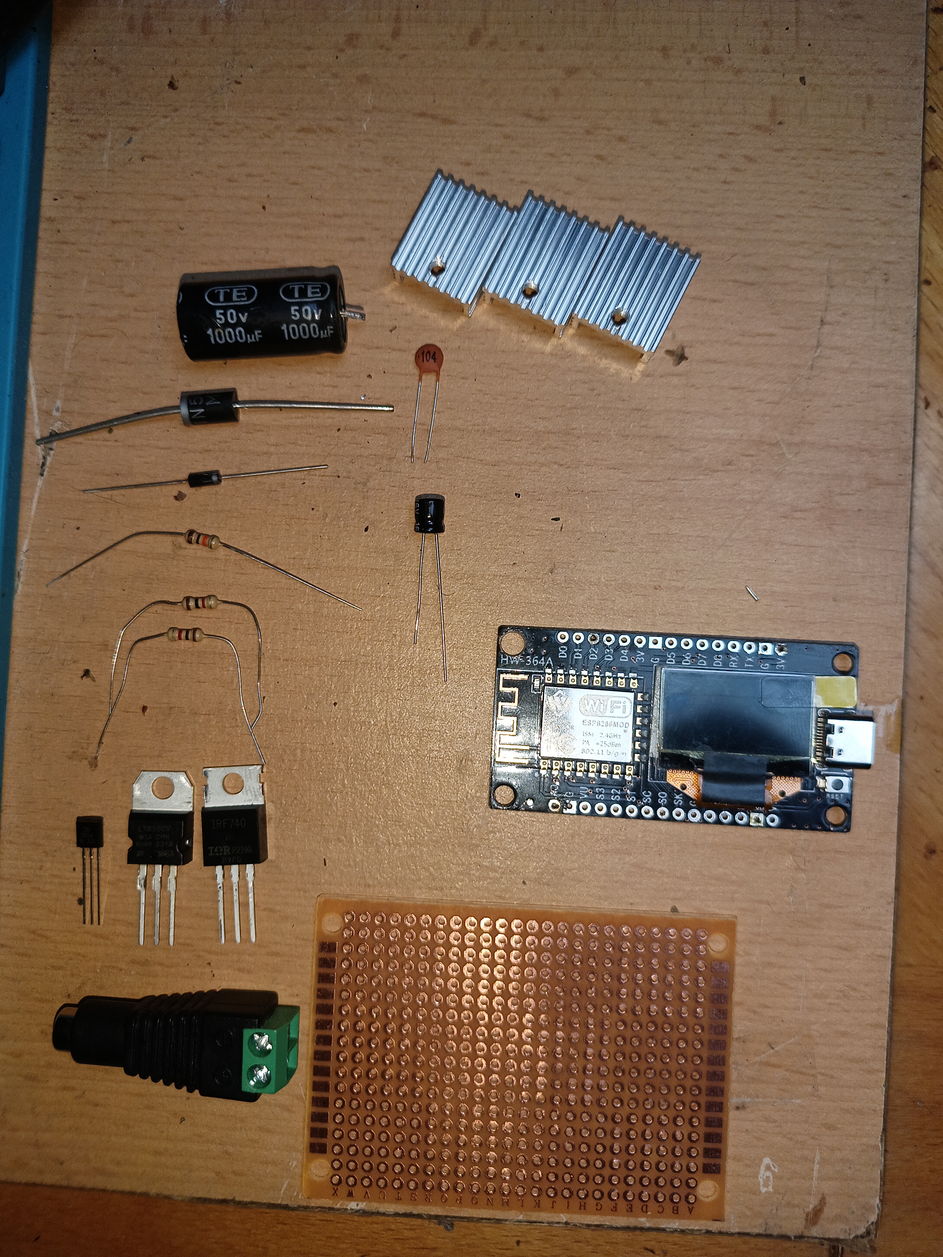
Before putting anything on the board, line up all your components to verify their dimensions and pin configurations:
-
ESP8266 Dev Board with built-in 0.96” OLED module
-
L7805CV Regulator + TO-220 Heatsink
-
IRF740 N-Channel MOSFET
-
2N3904 NPN Transistor
-
Diodes: 1N5408 (heavy-duty flyback diode for the 5A pump) and a smaller 1N4007 for general protection.
-
Capacitors: (or ), electrolytic, and ceramic.
-
Resistors: Two resistors, one resistor.
-
Screw Terminals: Wide-spaced screw terminals for the heavy-current power input (+12V/GND) and the motor output connections.
-
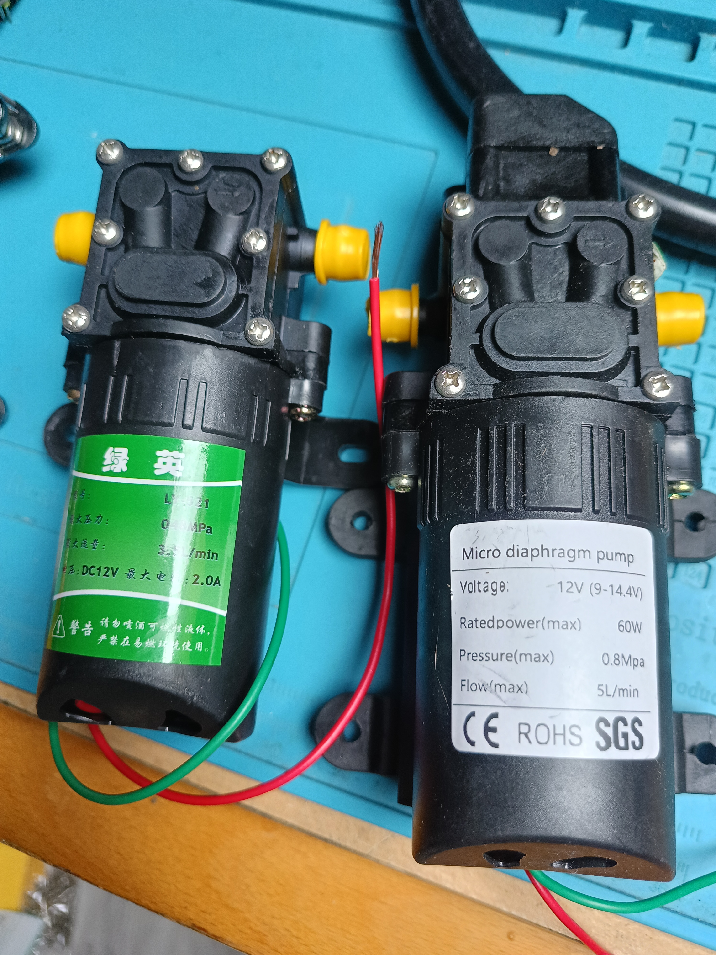
Water pump membrane motor 12V 5A - 60W
Step 2: Build Electrical Diagram and Code
The next step was to design elecrical diagram that would connect all pieces correctly. The AI helped to generate this useful Mermeid diagram that I was basic on.
graph TD
    %% Power Section
    PSU[12V 6A Power Supply] -->|+12V| V_IN[12V Main Rail]
    PSU -->|GND| GND_MAIN[Common GND Rail]
    V_IN --> C1[1000uF / 2200uF Cap]
    GND_MAIN --> C1

    %% 5V Logic Power
    V_IN -->|IN| REG[L7805CV Regulator + Heatsink]
    GND_MAIN -->|GND| REG
    REG -->|OUT +5V| ESP[ESP8266 5V/VIN Pin]
    GND_MAIN -->|GND| ESP_G[ESP8266 GND]

    %% Input Button
    ESP_BTN[ESP8266 D2 / GPIO4] --> BTN[Push Button]
    BTN --> GND_MAIN

    %% MOSFET Gate Driver (2N3904)
    ESP_OUT[ESP8266 D1 / GPIO5] --> R1[1kΩ Resistor]
    R1 -->|Base| NPN[2N3904 Transistor]
    GND_MAIN -->|Emitter| NPN
    V_IN --> R2[1kΩ Resistor]
    R2 -->|Collector| NPN

    %% MOSFET
    NPN -->|Collector| MOS_G[Gate: FQP50N06]
    GND_MAIN --> R3[10kΩ Resistor]
    R3 --> MOS_G
    GND_MAIN -->|Source| MOS_S[Source: FQP50N06]
    MOS_D[Drain: FQP50N06] --> PUMP_NEG[Pump Negative]

    %% Pump and Flyback Diode
    V_IN --> PUMP_POS[Pump Positive]
    PUMP_POS -->|Cathode / Stripe| D1[1N5408 Flyback Diode]
    PUMP_NEG -->|Anode| D1
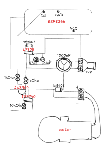
Then I started planning how to arrange all components on small through hole universal pcb board. After few attempts I drew this diagram that fit onto board straightly without complicated wiring.
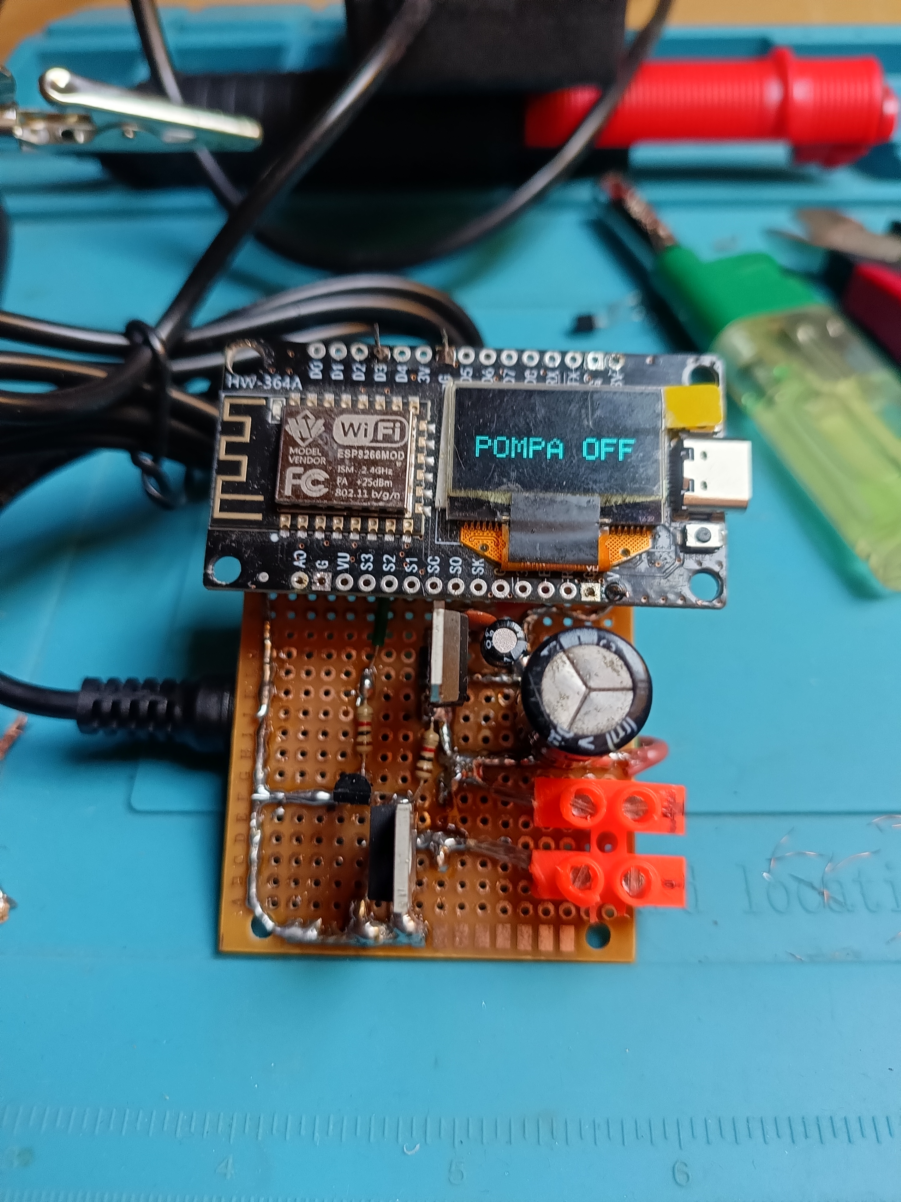
I soldered everything together. Maybe the paths are too thick especially for GND but I was told to make it more secure as the 4A current can flow through it.
Next part was to write the code to steer the pump. For first time I used awesome Arduino Cloud utility to build my thing there and I created my dashboard to control device.
#include <Wire.h>
#include <Adafruit_GFX.h>
#include <Adafruit_SSD1306.h>
#include "thingProperties.h"

#define SCREEN_WIDTH 128
#define SCREEN_HEIGHT 64
#define PUMP_PIN D3

// Declare the display using the I2C interface (-1 means no physical Reset pin)
Adafruit_SSD1306 display(SCREEN_WIDTH, SCREEN_HEIGHT, &Wire, -1);


void setup() {
  // Initialize serial and wait for port to open:
  Serial.begin(9600);
  // This delay gives the chance to wait for a Serial Monitor without blocking if none is found
  delay(1500);

  // Defined in thingProperties.h
  initProperties();

  // Connect to Arduino IoT Cloud
  ArduinoCloud.begin(ArduinoIoTPreferredConnection);

  /*
     The following function allows you to obtain more information
     related to the state of network and IoT Cloud connection and errors
     the higher number the more granular information you’ll get.
     The default is 0 (only errors).
     Maximum is 4
 */
  setDebugMessageLevel(2);
  ArduinoCloud.printDebugInfo();

  pinMode(PUMP_PIN, OUTPUT);

  // GPIO 14 = D5 (SDA), GPIO 12 = D6 (SCL)
  Wire.begin(14, 12);

  // Initialize display with its standard I2C address (usually 0x3C)
  if(!display.begin(SSD1306_SWITCHCAPVCC, 0x3C)) {
    Serial.println(F("OLED initialization failed!"));
    for(;;); // Loop infinitely if display is not found
  }

  // Clear the buffer and write text
  display.clearDisplay();
  display.setTextColor(SSD1306_WHITE);
  display.setCursor(10, 30);
  display.setTextSize(2);
  display.println(F("POMPA OFF"));

  display.display();
}

void loop() {
  ArduinoCloud.update();
  // Your code here


}

/*
  Since PumpState is READ_WRITE variable, onPumpStateChange() is
  executed every time a new value is received from IoT Cloud.
*/
void onPumpStateChange()  {
  // Write the current state of the cloud variable to the physical pin
  display.clearDisplay();
  display.setCursor(10, 30);
  display.setTextSize(2);

  if (pumpState == true) {
    digitalWrite(PUMP_PIN, HIGH);
    display.println(F("POMPA ON"));
  } else {
    digitalWrite(PUMP_PIN, LOW);
    display.println(F("POMPA OFF"));
  }

  // Push the memory buffer to the physical OLED screen
  display.display();
}